Ripple factor in a bridge rectifier is half than that of a half wave rectifier.
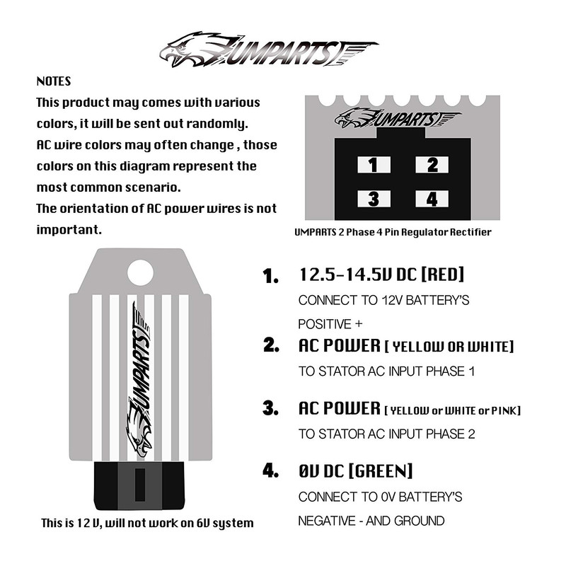
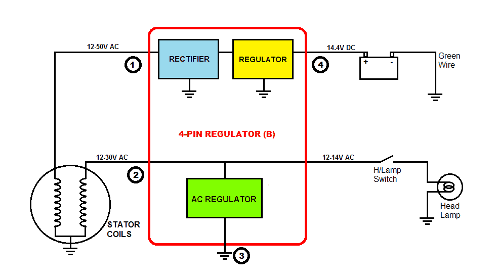
Half wave rectifier 12 volt 4 pin regulator rectifier wiring diagram.
Each diagram includes the part and associated parts all in one wiring diagram.
Probably an ok product for the right application but the documentation to tell what that application could be is lacking at best.
Trail tech stators have yellow lighting leads.
Trail tech regulator rectifier 7003 rr150 2 yellow wires.
In this video i show how to wire the rectifier regulator to the stator of the pitbike.
12v or 6v ct70 regulator rectifier pigtail click for instructions sub w 12 6 3 phase field excited revival cycles fx 5159 wiring 4 wire diagram free sparx single powerbox half wave solution puch and others moped army understanding motorcycle voltage homemade circuit projects check this out new a way better to in volt system increase output 12v read more.
Ripple factor in a bridge rectifier.
Regulator rectifier 7003 rr150 tech support.
3 phase rectifier voltage regulator schematic.
I also show how to.
By natalia kremen on june 24 2020 in wiring diagram 222 views.
To diagnose regulator faults a voltage tests is often sufficient.
Provided below is an online pdf document for lamberts bikes 4 pin regulator rectifier wiring diagram.
Full wave rectifier with capacitor filter.
Any lower and the regulator rectifier will not be able to charge the battery.
Ripple factor is a ratio of the residual ac component to dc component in the output voltage.
Use a multi meter set to volts dc.
3 phase rectifier voltage regulator schematic.
I only got about 6.
The ideal voltage range of the dc output should be between 12 3volts and 14 5volts.
The circuit diagram below shows a half wave rectifier with capacitor filter.
To explain the concepts better we have.
I show how to make connections for the headlight.
The worst part is that is is only a half wave rectifier and it would not put out 12 volts.
Like all good motorcycle engineers lamberts bikes have produced part specific electrical wiring schematics.
Connect to lighting leads from stator.
Now measure the output dc voltage at different engine rpm.


